

 |
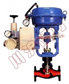 |
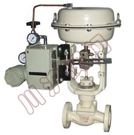
| HLS single seat pneumatic control valve | HLS single seat pneumatic control valve Internal structure |
HLS pneumatic control valve has the advantages of compact structure, with a streamlined S channel, the pressure drop, flow is large, wide adjustable range, the flow characteristics of high precision, conforms to the IEC534 standard. Valve leakage in line with ANSI B16.104 standard. Valve equipped with multi spring diaphragm actuator, which has the advantages of compact structure, large output force, the products comply with GB/T4213-92.
Type: straight through single seat casting ball valve
Nominal diameter: 20, 25, 40, 50, 65, 80, 100, 150, 200mm
Nominal pressure: ANSI 125, 150, 300, 600
JIS 10, 16, 20, 30, 40K
PN1.6, 4, 6.4MPa
Connection: flange connection type: FF, RF, RJ, LG, groove type, embedded type
Flange standards: JIS B2201-1984, ANSI B16.5-1981, GB/T9112 ~ 9124-2000
Welding weld connection: SW
Material: steel, cast stainless steel (ZG230-450) (ZG1Cr18Ni9Ti, ZG1Cr18Ni12Mo2Ti, ZG00Cr18Ni12Mo2Ti), titanium etc.
The valve cover: ambient temperature (P): -17 ~ +230 ℃
Elongation type Ⅰ (E1): -45 ~ -17 ℃ +230 ℃ to +566 ℃
Elongation type II (E2I): -100 ~ -45 ℃
Elongation type II (E2W): -196 ~ -100 ℃
Note: the temperature must not exceed the allowable range of various materials.
The gland bolts type: type
Packing: V PTFE, impregnated Teflon asbestos packing, asbestos braid packing, graphite packing
Valve components
Valve type: single seat plunger type valve
Flow characteristics: metal seat features such as the percentage (%) and the linear characteristic (L), the reference flow characteristic curve
The value of Cv conforms to the IEC534-2 standard from the high precision of flow characteristics of 0.04 ~ 14
Soft valve seat: the percentage of properties such as (%) and the linear characteristic (L), the reference flow characteristic curve
Note: for PTFE seat operating temperature and pressure difference, the reference flow characteristic curve
Material: stainless steel (1Cr18Ni9Ti, 1Cr18Ni12Mo2Ti, 17-4PH, 9Cr18, 316L), stainless steel cladding division Chatterley alloy, titanium and corrosion resistant alloy
| Model | ZHA/B-11 | ZHA/B-22 | ZHA/B-23 | ZHA/B-34 | ZHA/B-45 | ZHA/B-56 |
|---|---|---|---|---|---|---|
| stroke(mm) | 10 | 10、16 | 16、25 | 40 | 40、60 | 100 |
| Effective area(cm) | 200 | 350 | 350 | 560 | 960 | 1600 |
| D1(mm) | 32 | 60 | 60 | 80 | 95 | 100 |
| D2(mm) | / | 80 | 80 | 105 | 122 | 130 |
| n-d | / | 2-Φ10 | 2-Φ10 | 4 -Φ12 | 4 -Φ14 | 4 -Φ18 |
| M | M8 | M8 | M8 | M12×1.25 | M16×1.5 | M20×1.5 |
| S(ZHA/ZHB)mm | 80/70 | 100/84 | 100/75 | 154/114 | 180/115 | 260/160 |
| Air interface size | M10×1 | M12×1.25 | M16×1.5 | |||
| Air pressure | 0.14、0.25MPa | |||||
| Environmental temperature | -30~60oC | |||||
| Spring range | 0.02~0.10、0.04~0.10、0.08~0.24MPa | |||||
| Spool type | Valve seat and valve flow characteristics | Rated stroke | 0.01 | 0.04 | 0.1 | 0.16 | 0.25 | 0.4 | 0.63 | 1.0 | 1.6 | 2.5 | 4.0 | 6.3 | 10 | 14 | |
|---|---|---|---|---|---|---|---|---|---|---|---|---|---|---|---|---|---|
| Plunger valve | Metal valve seat | percentage(%) | 14.3mm | ○ | △ | △ | △ | △ | △ | △ | △ | △ | △ | ||||
| Line(L) | ○ | ○ | ○ | ○ | ○ | △ | △ | △ | △ | △ | △ | △ | △ | △ | |||
| Soft seat | percentage(%) | ○ | ○ | ○ | ○ | ○ | ○ | ○ | ○ | ○ | ○ | ||||||
| Line(L) | ○ | ○ | ○ | ○ | ○ | ○ | ○ | ○ | ○ | ○ | ○ | ○ | |||||
| DN | 20 | √ | √ | √ | √ | √ | √ | √ | √ | √ | √ | √ | √ | ||||
| 25 | √ | √ | √ | √ | √ | √ | √ | √ | √ | √ | √ | √ | √ | √ | |||
Note: 1, symbols, and △ said valve size range. 2, the symbol delta said the valve flow characteristics in accordance with IEC 534-2 standard.
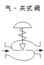
Ⅰ.Plunger valve, metal seat (%CF, LCF) A. gas closing valve 100KPa
 |
Actuator | Supply pressure | Spring range | Positioner | Allow pressure | ||||||
|---|---|---|---|---|---|---|---|---|---|---|---|
| Rated Cv | |||||||||||
| ≤0.25 | 0.4 | 0.63 | 1.0 | 1.6 | 2.5 | 4.0 | |||||
| HA1D | 1.4 | 0.2~1.0 | yes or no | 40 | 31 | 31 | 16 | 16 | 10 | 10 | |
| 56 | |||||||||||
| 1.6 | 0.2~1.0 | yes | 40 | 40 | 40 | 40 | 40 | 40 | 40 | ||
| 100 | 100 | 100 | 84 | 84 | 52 | 52 | |||||
| 4.0 | 0.8~2.4 | yes | - | - | - | 40 | 40 | 40 | 40 | ||
| 100 | 100 | 100 | 100 | ||||||||
| HA2D | 1.4 | 0.2~1.0 | yes or no | 40 | 40 | 40 | 32.6 | 32.6 | 20 | 20 | |
| 100 | 62 | 62 | |||||||||
| 1.6 | 0.2~1.0 | yes | - | 40 | 40 | 40 | 40 | 40 | 40 | ||
| 100 | 100 | 100 | 100 | 100 | 100 | ||||||
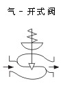
B.Gas - open valve
 |
Actuator | Supply pressure | Spring range | Positioner | Allow pressure | |||||||||
|---|---|---|---|---|---|---|---|---|---|---|---|---|---|---|
| Rated Cv | ||||||||||||||
| ≤0.25 | 0.4 | 0.63 | 1.0 | 1.6 | 2.5 | 4.0 | 6.3 | 10 | 14 | |||||
| LHA1R | 1.4 | 0.2~1.0 | yes or no | 7.2 | 7.2 | 7.2 | 7.2 | 7.2 | 7.2 | 7.2 | 4.0 | 2.9 | 1.8 | |
| 4.0 | 0.8~2.4 | yes | 30 | 30 | 30 | 30 | 30 | 30 | 30 | 27 | 20 | 12 | ||
| LHA2R | 1.4 | 0.2~1.0 | yes or no | 20 | 20 | 20 | 20 | 20 | 14 | 14 | 7.6 | 5.7 | 3.5 | |
| 4.0 | 0.8~2.4 | yes | - | 30 | 30 | 30 | 30 | 30 | 30 | 30 | 30 | 24 | ||
Note 1: the maximum allowable pressure must not exceed the specified ANSI B16.34 or JIS B2201 standard maximum working pressure.
2 black box number indicates valve with the standard actuator.
Flange distance
| DN | A | ||||||||||
|---|---|---|---|---|---|---|---|---|---|---|---|
| ANSI 125FF ANSI 150RF JIS 10K Ff,RF PN1.6 | JIS 16K RF | ANSI 300RF JIS 20K RF JIS 30K RF PN4.0 | ANSI 600RF JIS 40K RF PN6.4 | ANSI 150 RJ | ANSI 300 RJ | ANSI 600 RJ | JIS 20K Trench embedded type | JIS 30K Trench embedded type | ANSI 300 LG | ANSI 600 SW、BW | |
| 20 | 184 | 190 | 194 | 206 | - | 206 | 206 | 198 | 208 | 203 | 206 |
| 25 | 184 | 193 | 197 | 210 | 197 | 210 | 210 | 198 | 212 | 206 | 210 |
Actuator
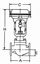 |
Actuator | H | φB | C | E | |||
|---|---|---|---|---|---|---|---|---|
| ambient temperature P | Elongation type Ⅰ E1 | Elongation type II E2I | Elongation type II E2W | |||||
| LHA1D、R | 375 | 525 | 685 | 900 | 218 | 230 | 40 | |
| LHA2D、R | 450 | 600 | 760 | 975 | 267 | 281 | 40 | |
Note: the table size is not H regulating valve with hand wheel digital, if with hand wheel, hand wheel mechanism to plus size.
 Sales Hotline:+86-021-5186 3046 Fax:+86-021-5186 3049 Mail:chvalve@126.com Address:Shanghai Fengxian District Jinhui Industrial Garden Jinbi Road No. 358
Copyright © Shanghai Chuanhu Valve Co. Ltd.
Sales Hotline:+86-021-5186 3046 Fax:+86-021-5186 3049 Mail:chvalve@126.com Address:Shanghai Fengxian District Jinhui Industrial Garden Jinbi Road No. 358
Copyright © Shanghai Chuanhu Valve Co. Ltd.